Building and testing the motor circuit
Hi everyone.
In the last post I showed the circuit diagram for the vibration motor, and most importantly I tried to actually spell out how and why the circuit is the way it is. Here I will be doing some good ol’ fashioned science, and test if the circuit works as I theorized in the last post. I need to do this because I’m not entirely sure that I’ve got everything right about the circuit.
Here’s the implemented circuit:
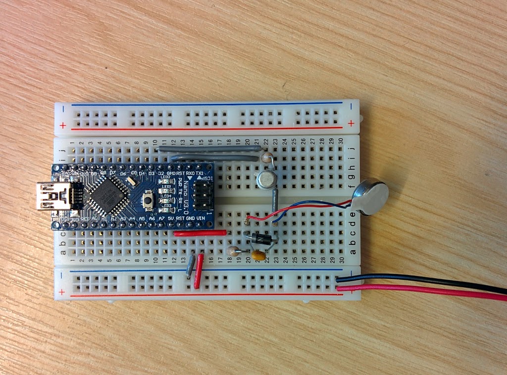 Top view
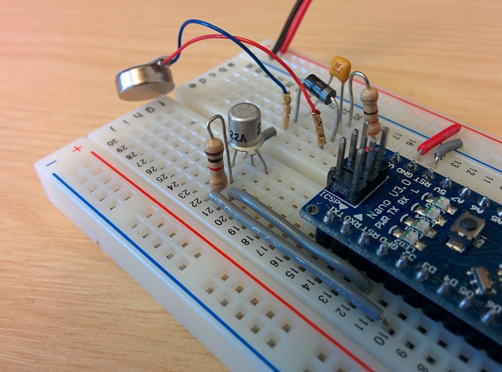 Details.
EDIT: there’s a mistake in this circuit, see here
For example, more than one friend expressed doubts on my statement that the transistor can’t draw more current than that’s available from the 5V paired with the resistances. The resistances would be the 33Ohm resistance + the resistance opposed by the motor.
The code driving the Arduino while I do the measurements is very simple:
const int vibmotor = 3

void setup() {
  pinMode(vibmotor, OUTPUT);
}

void loop() {
  // the duty cycle is a value from 0 to 255, where 255 corresponds to 100%
  digitalWrite(motor,0);
  delay(5000);
  digitalWrite(motor,128);
  delay(5000);
  digitalWrite(motor,255);
  delay(5000);
}
Measurements
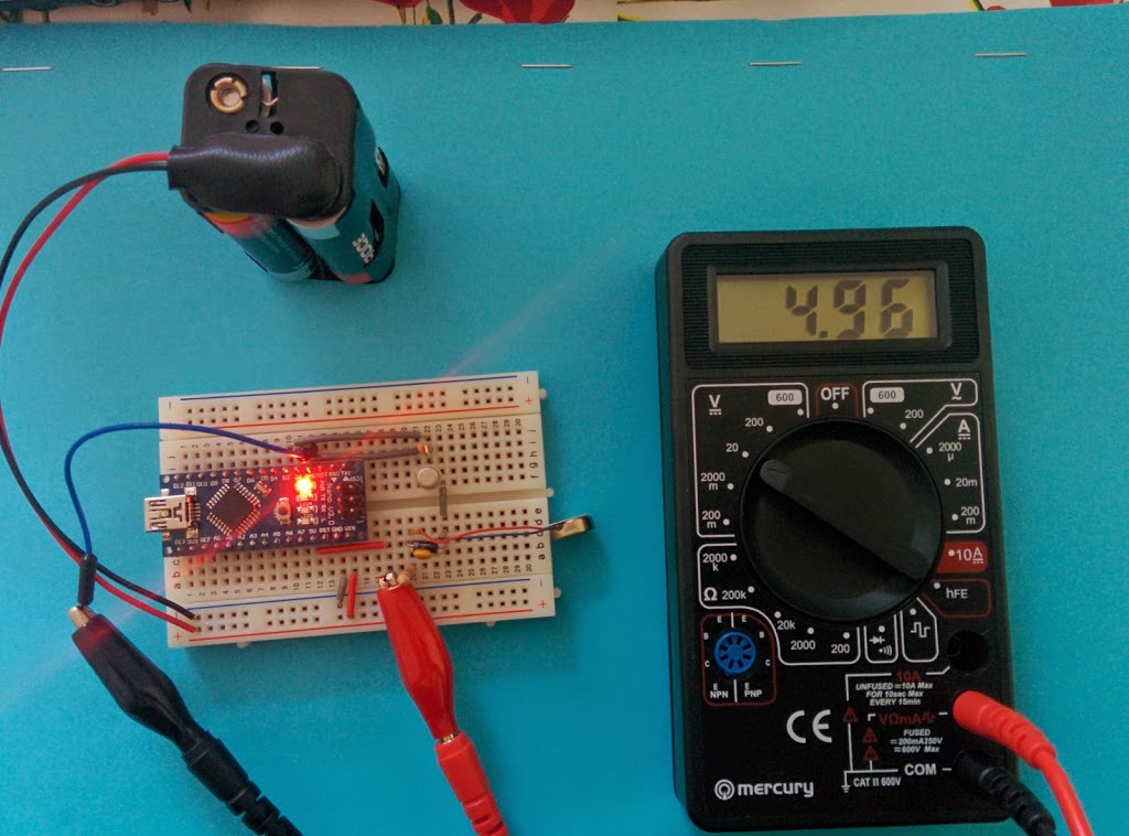
- The relationship between the Voltage from the 33Ohm resistor and the motor, so that I can figure out what’s the motor’s resistance.
- What’s happening to the transistor’s voltage.
- What happens when I change the duty cycle of the PWM.
| PWM duty cycle | 0% | 50% | 100% |
|---|---|---|---|
| Across 33Ohm resistor | 1 | 1.8 | |
| Across motor | 1.4 | 2.8 | |
| Across transistor (collector-emitter) | 4.8 | 2.4 | 0.03 |
| 5V pin to GND (whole circuit) | 4.8 | 4.77 | 4.7 |
| PWM duty cycle | 0% | 50% | 100% |
|---|---|---|---|
| Across 33Ohm resistor | 1 | 1.9 | |
| Across motor | 1.4 | 2.9 | |
| Across transistor (collector-emitter) | 4.96 | 2.4 | 0.04 |
| 5V pin to GND (whole circuit) | 4.96 | 4.94 | 4.91 |
- the transistor can't deliver more current than the one which is available from the 5V branch
- I can't use the full range of the PWM duty cycles, as if the transistor is multiplying by 100 its base current, then once reached a certain duty cycle, there will be not enough current from the 5V branch to satisfy the multiplication, and from that duty cycle on the current will just be the maximum current.
| PWM duty cycle | 0% | 50% | 100% |
|---|---|---|---|
| Current in mA | 28 | 56 |
Discussion of the measurements
From the measurements it seems that the voltage drop across the motor is more or less 1/2 more than that across the 33Ohm resistance. That means that the motor resistance is more or less 50Ohm. Which is quite far from the 75Ohm terminal resistance stated in the datasheet. So, either the terminal resistance is not what I think it is, or other factors are in play in determining the resistance of the motor.
Another surprise from the measurements is that I didn’t think about the resistance in the transistor when calculating the voltage drops in the circuit in the last post. What I discovered is that the transistor acts like a variable resistor.
Now for my hypotheses in the last post. Let’s repeat them for clarity.
- The transistor can’t deliver more current than the one which is available from the 5V branch.
- I can’t use the full range of the PWM duty cycles, as if the transistor is multiplying by 100 its base current, then once reached a certain duty cycle, there will be not enough current from the 5V branch to satisfy the multiplication, and from that duty cycle on the current will just be the maximum current.
The 1st hypothesis is supported by observation, while the 2nd turns out to be false.
While it seems it is true that the transistor can’t draw more current than what’s available from the 5V branch, apparently the whole range of duty cycles can be used to modulate the current flowing through the Collector-Emitter. A 100% duty cycle lets more or less all the available current flow, whereas a 50% duty cycle lets half of it flow. I’m not sure why this is, I’ll have to read more on transistors.
By the way, to collect more evidence on the fact that the transistor can’t let more current than the one that’s available from the 5V branch, I repeated the measurements without the motor, so that the only resistances in the 5V branch were the 33Ohm resistor and the transistor. As expected, with 100% duty cycle, the transistor just lets all the available current through (and not more).

In the next post, I’ll plug the ultrasonic sensor in and I’ll experiment a bit with it, showing you some code in the meantime.
I’ll keep you posted!
BAT NAVIGATOR
arduino bat navigator