Nearly burned a pin
Hi everyone.
First things first, I have to tell you that I’ve made a huge mistake in the circuit I showed you last time.
 I have something in common with Gob today
Today, as I added the ultrasonic sensor, I decided to measure the entire circuit consumption. It was around 160 mA. Now that just wasn’t right, given that I knew the consumption for the motor branch and I knew that the ultrasonic sensor
only needs more or less 15mA of current. So I ended up measuring the current from the data pin, noticed that something was very wrong, and spotted my mistake.
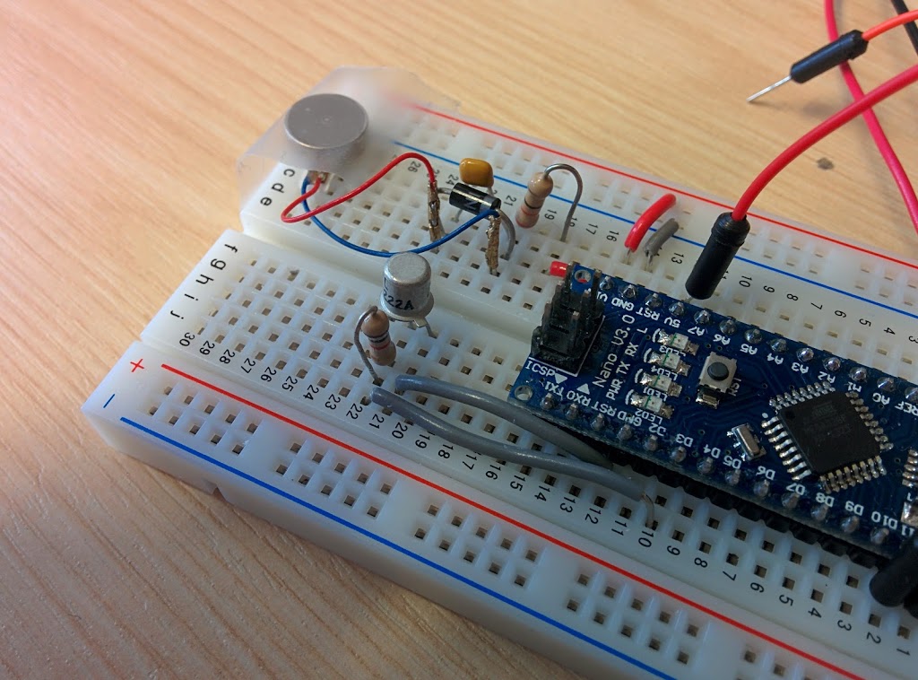
This is the way I connected the D3 data pin resistance last time:

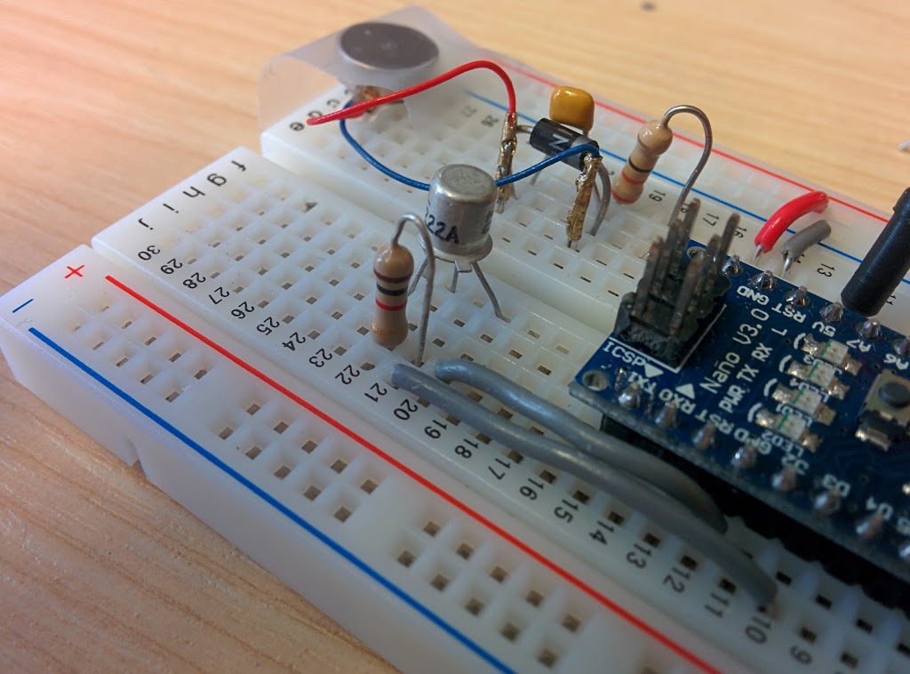
This is the way I should have connected it:

In the first image, the resistance is useless, as the bread board pins are connected in rows. The circuit is shorted, and the resistance does practically nothing. Remember that that resistance is needed to avoid burning the data pin, which can handle 40mA current tops. The situation is fixed in the second picture, as the resistance connects two different rows. I risked burning that data pin.
Now, why didn’t I notice that before? Because last time I didn’t measure the current in the whole circuit, including the Arduino, but only from the 5V pin to the ground pin. So I was only measuring the current in the motor branch, and I had no information on what was happening in the rest of the circuit.
I decided not to edit the last post and to write a new one instead, as one of the reasons I keep this blog is to document what I learn out of my side projects. Making mistakes is part of learning, and hopefully writing this post will help me avoid doing the same mistake again.
Anyway, as I already told you, I added the ultrasonic sensor to the circuit. I’ll soon upload my experiments with it and the code I used to run them.
I’ll keep you posted!
BAT NAVIGATOR
arduino bat navigator